
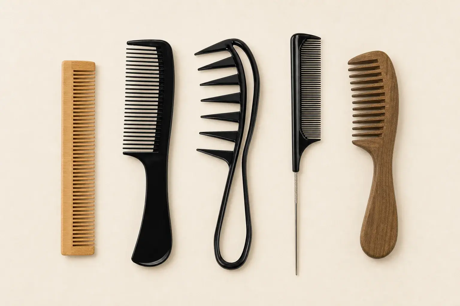
A comb can look finished in a reference photograph while most of its working decisions remain open. The picture may show a slim tail, a wide grip, or a curved spine. It rarely establishes the actual scale, body thickness, tooth-zone length, edge condition, package fit, or the dimensions that production must hold.
A useful shape brief turns those visual cues into one controlled product definition. It gives the teeth enough working space, places the hand on a deliberate grip, reserves room for branding and packaging, and marks the details that still need feasibility review.
LuxoComb uses 90 to 230 mm as a typical overall length reference, with custom dimensions reviewed for the project. That range helps with early orientation. The finished shape still follows the grooming task, tooth layout, material, handle or tail, components, and carry format.
Start with the working action and hand position
Write down the main action before choosing the silhouette. A cutting comb, sectioning tail comb, wide-tooth comb, pocket comb, beard comb, and hotel comb use their available length in different ways. A project that names several possible uses should still identify the action that receives priority.
Describe how the user holds and moves the comb. Mark the grip area, hand orientation, working direction, required reach, and any surface that approaches hair, scalp, or skin. This information gives the handle, curve, end profile, and tooth field a reason to take their proposed form.
The word ergonomic cannot carry the brief by itself. Show where the fingers sit, how the product is oriented, which edge meets the hand, and what the physical sample should prove during use.
Set the overall envelope before shaping the details
The overall envelope begins with maximum length, width, and thickness. Add the front profile, side profile, ends, corners, spine, handle, tail, curves, holes, cutouts, covers, and attached components. A single top view can hide thickness changes and assembled relationships.
Show front, side, and section views wherever the body changes depth or curvature. Locate important features from agreed reference edges or centerlines so every dimension refers to the same product position. Identify the drawing units and scale.
The complete envelope includes the finished product in its normal state. A folding comb needs open and closed views. A fixed pocket comb may need a paired view inside its sleeve. A comb developed for a kit needs its proposed orientation and removal space inside the insert or pouch.
Separate fixed, preferred, and open points
A brief becomes easier to review when every important point carries a priority. Fixed points must remain as stated. Preferred points express the intended direction and can move after discussion. Open points invite a proposal based on material, process, tooling, assembly, or package fit.
Use the same labels for dimensions and visual features. Overall pack length may be fixed, the handle curve may be preferred, and the exact transition into the tooth zone may remain open. This makes a feasibility change visible before it enters a revised drawing.
Separate critical dimensions from reference dimensions after the design develops. Critical dimensions control use, assembly, or packaging and need an agreed measurement and acceptance approach. Reference dimensions help explain the shape without creating a second requirement for the same feature.
Use reference products with measured intent
A sample, photograph, sketch, CAD file, or annotated image can begin the discussion. Mark what the reference contributes. It may supply the grip direction, outline, tail concept, tooth-zone order, or package relationship while other details remain available for change.
Measure any feature that needs to survive the translation into a new product. A request to make the whole reference ten percent shorter can distort tooth spacing, tooth length, grip room, logo proportion, hole size, wall thickness, and package clearance at the same time.
Keep the source reference identified with the project. Record which features are copied, adapted, or newly drawn. The controlled drawing becomes the production reference once the dimensions and revisions have been approved.
Allocate the available length across teeth, grip, and structure
Divide the overall body into working tooth zones, transitions, spine, grip or handle, tail, end profiles, holes, pivots, and clearances. Every addition uses part of the same envelope. A compact body may lose useful tooth length when the concept also asks for a large logo, generous grip, second tooth zone, hanging hole, or decorative end.
Give each fine, wide, or mixed tooth zone a purpose, position, and working length. Then define the related tooth spacing convention, tooth length, width, taper, roots, tips, and transition on the geometry drawing. This article keeps the focus on where the zones sit within the full shape.
Place the hand on the remaining body and check whether it blocks either zone. A tail comb needs enough sectioning reach and a controlled transition from body to tail. A handled wide-tooth comb needs enough room for the hand without crowding the nearest teeth.
Choose a handle format from the working position
| Shape direction | Space it protects | What the sample should prove |
|---|---|---|
| Handleless body | Compact size or a long uninterrupted tooth field | Grip location, orientation, thickness, and edge contact |
| Straight handle | A separate grip and clear working direction | Handle length, width, balance, and logo position |
| Curved handle | A shaped hand position or curved working path | Curve, pressure points, orientation, and feasibility |
| Tail handle | Sectioning reach and precise placement | Tail length, straightness, tip, and body transition |
| Shaped grip | A broader or more directed holding area | Finger position, hand clearance, balance, and edges |
These rows describe design directions. The selected material and production route determine the feasible detail, section thickness, edge treatment, and route to a representative sample.
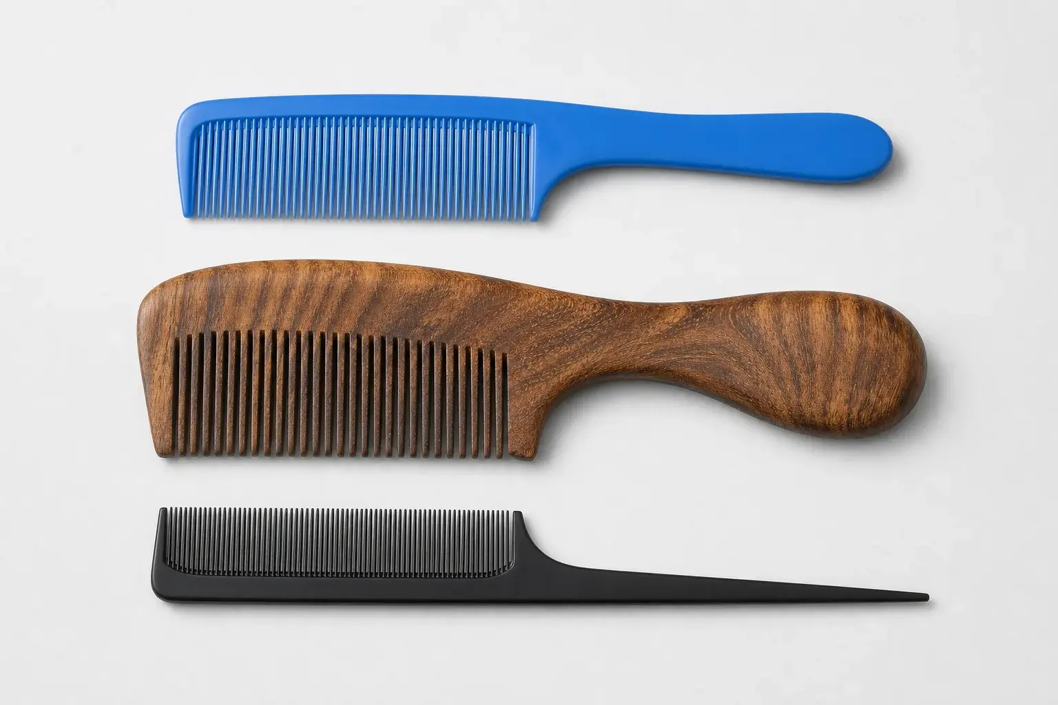
Show thickness, curves, and edges in more than one view
Overall length and width describe only the footprint. The side and section views should show body thickness, local changes, tapers, recessed areas, raised grips, edge profiles, and any curve that changes how the comb sits in the hand or package.
Locate the beginning and end of every curve. Mark the profile around contact edges and the transition between the tooth body and handle or tail. When a hole or cutout passes through the product, show its position, dimensions, and relation to the nearest edge.
Complex surfaces may need a CAD model or a physical reference in addition to the 2D drawing. The approval package should still contain measurable overall and critical dimensions, named views, and a revision that everyone can identify.
Match the shape to the material and production route
Injection-molded plastic, machined cellulose acetate, and shaped wood or bamboo reach a comb profile through different work. The same outline can require different body sections, tooth roots, corner treatment, surface review, and tooling decisions in each material.
Molded structures need review for the proposed resin, mold route, release, surface, and part geometry. Acetate begins with a selected sheet and uses cutting, machining, sanding, and polishing. Wood and bamboo need cutting, tooth processing, sanding, finishing, and attention to the selected material direction.
Place the proposed material on the drawing and mark any detail that can change during feasibility review. Transfer the visual intent while allowing the section, root, edge, or joint to follow the confirmed route. The material selection page helps separate those project decisions.
Draw holes, pivots, mirrors, and attached components
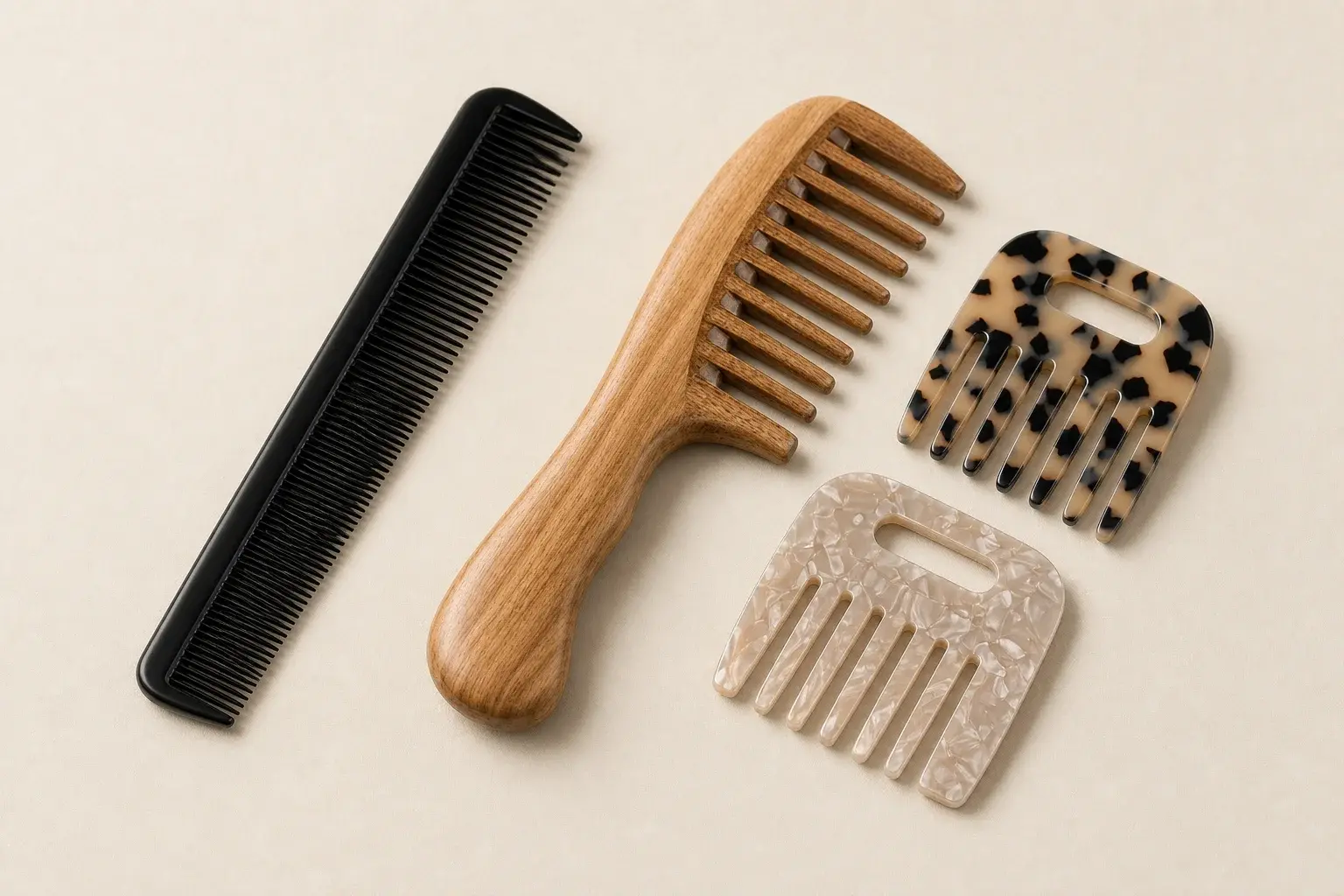
A hole, cover, fastener, mirror, insert, or moving part changes the shape around it. Show the component size, position, mating surfaces, attachment, and any required clearance. Identify the product state in which each dimension applies.
Folding structures need open and closed dimensions, pivot position, stop position, tooth coverage, component fit, and the movement path. A mirror or decorative insert changes internal space, pressure points, visible gaps, and package protection.
Review the complete assembly on a physical sample. An approved flat comb insert and an approved handle still leave alignment, movement, fit, and contact between the parts to be checked.
Reserve branding space after the working areas
Place the tooth field, grip, tail, contact edges, holes, and moving relationships first. The remaining surface shows the realistic branding area. Mark the artwork size, position, orientation, method, color reference, and clearance from nearby features.
A logo can read differently when the product is held, packed, displayed, or closed. Show the intended viewing direction. Folding combs may need separate open and closed artwork views, while pocket combs may pair branding on the body with another placement on the sleeve.
Approve the logo on the correct material, finish, color, and product revision. The logo placement guide carries artwork clearances and sample checks into the decoration review.
Draw the finished product inside the unit package
Package size can set the maximum comb envelope before the first sample is made. Draw the finished body inside the sleeve, pouch, card, tray, box, or kit. Mark orientation, insertion direction, removal space, tooth protection, and any area that may receive pressure.
Include the handle, tail, pivot, mirror, raised feature, or curved surface that controls fit. A flat outside dimension can miss the part that touches the insert or makes the product difficult to remove.
Keep product and packaging revisions linked. A later change to the comb thickness, curve, tooth length, or handle can require another structural fit review. The packaging brief separates structural approval from printed artwork approval.
Build one controlled drawing for review
Start with the product name, units, scale, revision, and view labels. Add the overall envelope, reference edges, tooth zones, handle or tail, thickness sections, curves, holes, components, material, surface, branding area, and package interface.
Identify fixed, preferred, and open points during concept review. Once feasibility has been agreed, mark the critical dimensions, measurement conventions, confirmed tolerances, and any order-specific acceptance notes. Keep tooth, component, artwork, and package details on the same revision or link their controlled files clearly.
Record every change through a new revision. A marked photograph can explain one correction, though any change that affects production or inspection should be added back to the controlled drawing.
Approve the shape on a physical sample
The drawing controls measurable requirements. The physical sample shows proportion, grip, contact edges, balance, surface, tooth function, component fit, movement, branding, and package fit in the complete product.
Use the sample through the agreed action. Hold it in the stated orientation, work with every tooth zone, reach with the tail where relevant, open and close any moving part, insert it into the unit pack, and remove it again. Measure the dimensions that control these actions using the agreed method.
Keep the identified sample with the drawing revision, material and color references, artwork, marked photographs, package specification, and written decision. The sample approval checklist helps separate approved, conditional, and revised points.
Prepare the shape and size brief
Send the intended grooming task, user, hand position, working direction, overall envelope, primary and secondary tooth zones, handle or tail direction, material preference, components, logo, package, quantity, destination, and required documents.
Add a sketch, 2D drawing, CAD file, annotated image, or physical sample. Mark the details that must stay, the features that express a preference, and the areas available for proposal. This gives the feasibility review a clear starting point without treating an early reference as a finished production specification.